Problem 1
Step-1
Windows 7
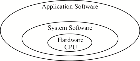
An operating system known as OS is system software which bridges between user and the hardware of the computer. The main goal of the operating system is to make use of computer system convenient while using hardware to the optimum level.
Operating system can be categorized on the basis of their looks and architecture support other than the supported features. The table given below shows the categories.
| S No. | Look type | Architecture Support |
|---|
- | Non-GUI | 16 – bit
- | GUI | 32 – bit
- | | 64 – bit
The diagram given below shows the relation between the computer hardware and application software, to be used by the end user.
Step-2
Windows 7 is a product of Microsoft and is the most advanced Windows, with enhanced features and benefits. It comes in two variants to support both 32 – bit or 64 – bit architecture. Windows 7 is a multiuser GUI operating system which supports multitasking functionality for the user.
Few of the primary features enhanced in windows 7 over previous versions of Microsoft windows are as follows:
| S No. | Features |
|---|---|
| 1. | Direct Access – it is a new feature which allows user to connect to corporate network without need to access Virtual Private Network (VPN). |
| 2. | Branch Cache – Branch cache helps in improving the data access speed from a remote location. |
| 3. | Geo tracking – Windows 7 supports geo tracking feature for user. User has to define which applications access the geo location for the user. |
| 4. | Enhanced Security – All the registry settings, system objects and kernel are protected under the Access Control List security settings. |
| 5. | Two operating system personalities – Windows 7 gives support to two distinct operating system personalities that is Win32 and POSIX. |
| 6. | Virtual Desktop Infrastructure – the VDI model supports multiple virtual desktop deployment centralizing the user data, application software and windows configuration. |
Two major features for windows 7 are as given below:
| Feature One | Feature Two |
|---|---|
| Automatic Repair – Whenever any problem is detected with the startup, the OS launches the automated diagnostic trouble-shooter, which helps with both the OS problem and application problem. | The latest version of windows has been enabled to use TRIM command while reading or writing data on the Solid State Drives (SSD). This reduces the frequency of writes and flushes in lieu increasing the speed for data access from the drive. |
Problem 2
Step-1
Windows Design Goal
Windows 7 is a product of Microsoft and is the most advanced Windows, with enhanced features and benefits. It comes in two variants to support both 32 – bit or 64 – bit architecture. Windows 7 is a multiuser GUI operating system which supports multitasking functionality for the user.
After windows Vista, the primary goal while designing windows 7 was security, reliability, portability, language support and high performance. To achieve this goal below given functionality were added.
| S No. | Features |
|---|
- | Direct Access – it is a new feature which allows user to connect to corporate network without need to access Virtual Private Network (VPN).
- | Branch Cache – Branch cache helps in improving the data access speed from a remote location.
- | Geo tracking – Windows 7 supports geo tracking feature for user. User has to define which applications access the geo location for the user.
- | Enhanced Security – All the registry settings, system objects and kernel are protected under the Access Control List security settings.
- | Two operating system personalities – Windows 7 gives support to two distinct operating system personalities that is Win32 and POSIX.
- | Virtual Desktop Infrastructure – the VDI model supports multiple virtual desktop deployment centralizing the user data, application software and windows configuration.
Two major features for windows 7 are as given below:
| Feature One | Feature Two |
|---|---|
| Automatic Repair – Whenever any problem is detected with the start up, the OS launches the automated diagnostic trouble-shooter, which helps with both the OS problem and application problem. This feature catches the errors generated at user level and tries to find a solution within. | The latest version of windows has been enabled to use TRIM command while reading or writing data on the Solid State Drives (SSD). This reduces the frequency of writes and flush in lieu increasing the speed for data access from the drive, accelerating the I/O performance and reduces the CPU bottleneck. |
Problem 3
Step-1
Windows 7 Booting process
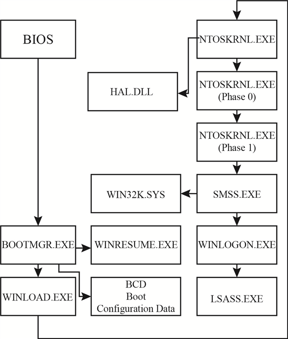
The process of getting a computer, soon power is turned on, into a state ready for accepting the input from the user and/or executing the applications is known as booting. The booting process is executed in steps one after the other.
Sooner the power is turned on; computer performs a self-test known as power-on self-test (POST). In POST the computer detects the devices which are attached and ready for use.
Step-2
After detection of the devices, disk is searched from which the BOOTMGR program is executed. The BOOTMGR program checks if any hibernation state for the system is saved. If hibernation state is found then the program WINRESUME is loaded to restore.
BOOTMGR checks the Boot Configuration Data for mounts and extracts the boot information. After BCD mounts the control is passed to WINLOAD program.
The WINLOAD program loads the NTOSKRNL and HAL.DLL programs along with the system hive which stores details of the system registry and boot drivers.
Step-3
The initialize the system kernel program NTOSKRNL uses two phases. In the phase 0 , the display driver for the system is initialized. The phase 1 sets the time bias and further calls SMSS program.
NTOSKRNL passes the control to SMSS the session manager subsystem. SMSS loads the device drivers, establishes the paging files for the system and manages the sessions for the windows logged-in users. SMSS also maintains a special session for maintaining the system services such as LSASS. Each SMSS session except for the one which is handling background services, runs the WINLOGON process. Each WINLOGON process is launched when a user logs in and corresponding EXPLORER process is executed.
Step-4
The booting process flow for windows 7 is as shown below.
Problem 4
Step-1
Windows kernel architecture
Windows kernel is a link between the computer hardware and application software. Its basic work is to manage the security levels, manage the virtual memory space usage, and multiple threads created for the execution of tasks without creating a deadlock condition.
Step-2
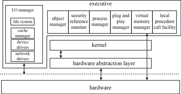
Windows kernel has three main layers in its architecture, which are:
a. Hardware Abstraction Layer (HAL)
b. Kernel
c. Executive Layer
Step-3
Explanation :
Hardware Abstraction Layer - HAL is a software layer which is in direct contact with the hardware of the computer system. HAL provides a non-real hardware interface to be used by the device drivers and the executive layer. The device is directly accessed by the device driver after being mapped. Other requirements which involve the chipset details like handling I/O buses, memory mapping, DMA are all handled by the HAL itself.
Step-4
Kernel – The basic role of Kernel is to handle the interrupts and exceptions along with scheduling the process and its threads and communicating between the user and Kernel. For every executable code there is a process assigned and with that process multiple related threads are executed. The purpose of Kernel is to handle these threads and keep a watch on any interrupt or exception caused due to these threads. It manages the various stages of the thread execution and the process flow accordingly.
Step-5
Executive Layer – The executive layer of the windows kernel provides support and services to the subsystems for all the users. It handles the virtual memory for each subsystem, manages the processes, handles all the procedure calls creating an interrupt, and other system managements like plug and play, registry, and cache.
Step-6
The diagram given below shows the three architectural layers in the Kernel.
Problem 5
Step-1
2481-22-14E AID: 268
RID: 944
Job of the object manager
Windows XP uses a generic set of interfaces to manage kernel-mode entities that are manipulated by user-mode programs. Windows XP calls these entities objects, and the executive component that manipulates them is the object mange.
The main job of object manager is to organize the allocation and use of all managed objects. Object manager maintains the Window XP internal name space. In contrast to UNIX, which roots the system name space in the file system, Window XP uses an abstract name space and concepts the file system as device.
Step-2
The object manager provides interfaces for defining both object types and object instances, translating names to objects, maintaining the abstract name space, and managing object creation and deletion. Objects are typically managed through the use of reference counts in protected-mode code and handles in user-mode code.
Step-3
The object manager keeps track of two counts for each object. The pointer count is the number of distinct references made to an object. Protected-mode code that refers to objects must keep a reference on the objects to ensure that an object is not deleted while in use. The handle table entries referring to an object. Each handle is also reflected in the reference count.
Problem 6
Step-1
Process Manager Services
A process is created for every executable code and application along with the related threads handling the process. All the stages of a process and its related threads are handled by the process manager and process manager provides services for the same.
Various stages of a process managed by the process manager are:
a. Creating a process
b. Using the process
c. Managing the threads
d. Remove the process
Step-2
Services involved in the various stages of a process managed by the process manager are as given below:
The process manager is involved only in the execution of the process but is not at all related to the process hierarchy. The process manager cannot schedule a process but can change the priority of the process (or its related threads) depending on the interrupts raised.
Step-3
Another service provided by the process manager is to implement Asynchronous procedure calls for the threads related to the process. Process manager creates a queue for the threads. The process manager also manages service to handle the local procedure call (LPC). LPC is a bridge to pass the request from client to server process and result from server process to client process.
Step-4
A thread can be allocated to a different process when in the executive layer. To manage this shift in the thread the process manager supports impersonation service. The process manager assigns a security token to each thread. The token assigned contains the security identity (SID) of the user authenticated by the login process.
Problem 7
Step-1
I/O manager responsibilities
The Input/output manager also known as I/O manager controls the flow of the process in association with other managers.
Device Driver – the I/O manager keeps a track of the device drivers which are loaded and controls the filter drivers, to manage the buffer memory requests for any specific drive or process I/O. The I/O stack maintains a list of device drivers attached to each device. The device object represents a driver in the system as a single driver can work on multiple devices.
Memory Mapped file - the I/O manager while handling the caching of the I/O system communicates with Windows Cache Manager and VM manager to provide links in the memory.
A synchronous I/O queue is maintained while any of the I/O operation is in wait state, by the I/O manager. Any I/O request received is converted to standard form I/O request packet (IRP) by the I/O manager. For processing this IRP is sent to the first driver in the I/O stack. After processing of the IRP the I/O manager either sends the IRP to the next driver in the I/O stack or if the process gets over return to the process manager.
Filter Drivers – when the I/O manager creates the I/O driver stack, then few drivers are inserted in the stack and they are called the filter drivers. I/O manager uses these filter drivers are given precedence over the file system and are used to provide the I/O flow to the system processes such as partition management or device mount management.
Problem 8
Step-1
2481-22-17E AID: 268
RID: 944
Responsibilities of I/O manager
The main responsibilities of I/O manager are
• File systems
• Device drivers
• Network drivers
It keeps track of which device drivers, filter drivers, and file systems are loaded, and it also manages buffers for I/O requests. It works with the virtual memory manager to provide memory-mapped file I/O and controls the windows XP cache manager, which handles caching for the entire I/O system.
Step-2
The I/O manager is fundamentally asynchronous, providing synchronous I/O by explicitly waiting for an I/O operation to complete. The I/O manager provides several models of asynchronous I/O completion, including setting of events, delivery of APCs to initiating threads, and use of I/O completion ports, which allows a single thread to process I/O completions from many other threads.
Problem 9
Step-1
Networking Protocols
The Client-Server architecture and Peer-to-Peer architecture for networking are both supported by windows 7. Both the architectures have a different outlook and working methodology.
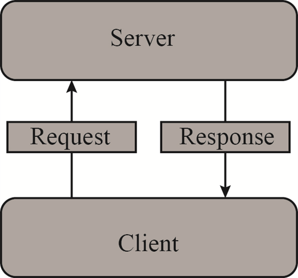
Client - Server Architecture:
In client-server architecture the end user requests the server for data, resources before processing. The processing can be done either by the client system or by the server. The best example to explain client server architecture is Web site – especially free email sites like Gmail. The client (the email account user) accesses the home page of the service provider – Gmail. When client enters the details (username and password) then the information is sent to the server for authentication. Server processes the information and upon authenticating responds back to the client with access to the emails.
Step-2
The diagram given below shows the link between client and server in client-server architecture.
Step-3
The client-server architecture starts working sooner the Uniform Resource Locator (URL) is triggered. The server is sent a request stating that a client is requesting for the home page and server responds back with the home page (if user is authorized). Similarly, whenever any download request is sent from the client, then too the client-server architecture for network is executed.
Step-4
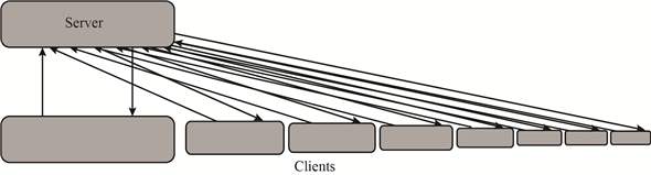
In client-server architecture, the server can respond to multiple users at the same time. When a client is added to the server the load on the server increases; for server needs to cater the needs of each client.
When the number of clients requesting from server crosses the limit for number of clients which server can handle, then the website crashes, and become inaccessible.
The diagram given below shows the links between clients and server in client-server architecture.
Step-5
P2P Architecture
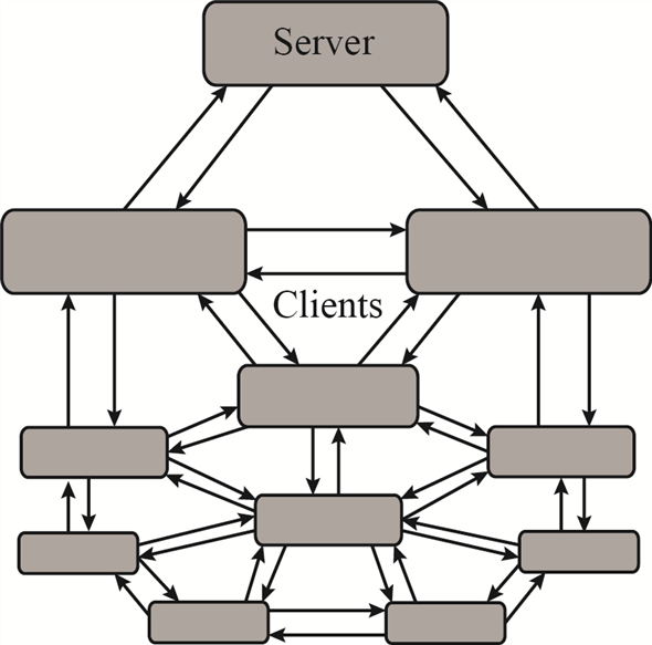
In peer to peer architecture, also known as P2P architecture, server is involved with the client – similar to the client-server architecture. The difference is that in P2P the client does not necessarily need to wait for the server to reply for the request but sends the request to all available clients. Any client which can cater to the needs of another client does so reducing the load on the server.
In another way it can be said that in P2P architecture each client who is responding to request of any other client is labelled as server, though not exactly having features of a server.
The P2P architecture can be shown by the diagram as shown below:
Step-6
Transmission Control Protocol/Internet Protocol (TCP/IP) is the protocol suit which is used by default by all networking tasks. TCP/IP is way ahead in use over other networking protocols.
To maintain networking architecture, Windows 7 also has IPX/SPX and NetBEUI protocols. The protocol IPX/SPX is used to share the resources over the network. IPX/SPX is used for file and printer sharing over the network.
Transmission Control Protocol/Internet Protocol (TCP/IP) is the protocol suit having various networking protocols which work at different layers in the network model. To name a few – in Application layer (DHCP, FTP, POP, SMTP etc), Transport layer (TCP, UDP etc.)
Two protocols FTP and DHCP are explained below:
-
File Transfer protocol (FTP) – is part of the protocol suit. It is used when two computers on a network need to exchange files. It allows sharing of files through remote computers. It maintains a privacy of users sharing same file. It is also efficient and reliable in data transfer.
-
Dynamic host configuration protocol (DHCP) – is used to dynamically assign the IP address to the computers on a network. The IP’s are allocated from a pool of IP address to each machine connecting to the network. The IP address is released sooner the machine goes off the network. This entire process is managed by the DHCP on the client machine and the DHCP settings of the server in the client-server networking architecture.
Problem 10
Step-1
NTFS namespace
The New Technology File System (NTFS) supports encryption of volume or individual files, and uses ACL’s to control access for the same. Many other features are implemented on the files by the NTFS, like fault tolerance, file compression.
In the NTFS namespace, directories are stored in the hierarchical patter similar to  tree of Data Structure. In B+ tree the top most node contain its child nodes, similarly in NTFS the files or sub-directories in one directory are maintained as child of that specific directory.
The traversal from the root node to the leaf node gives the path for the leaf element from the index root. Each entry in the NTFS namespace B+ directory node contains the name and reference of the file, along with the time stamp of the file and its size. All the details regarding the file name, time stamp, size, and file reference are available in the directory tree, reducing the need of the Master File Table (MFT) access each time a file is accessed.
Problem 11
Step-1
New Technology File System
The NTFS file system is designed for many futures, including data recovery, security, fault tolerance, large files and file systems, multiple data streams, and so on. The NTFS does not deal with individual sectors of a disk but instead uses clusters as the units of disk allocation.
Data structure handling by NTFS:
Every file in the NTFS is described by one or more records in an array stored in a special file called the master file table. The size of a record is determined when the file system is created and the size ranges from 1 to 4 KB. In the NTFS system, before the data structure is altered, transactions write a log record containing redo and undo information.
Step-2
The NTFS namespace is organized as a hierarchy of directories. Each of these directories uses a data structure called a B+ tree to store an index of the file name in that directory. NTFS uses B+ trees because the length of every path from the root of the tree to a leaf is the same and the cost of reorganization of the tree is eliminated.
Step-3
NTFS recovery from a system crash:
For recover NTFS processes the log records, first redoing operations for committed transactions and undoing operations for transactions that did not commit successfully before the crash.
Step-4
The things guaranteed after recovery:
There is no guarantee that all user file contents are correct after recovery, because the file contents are modified based on log file after a recovery. It ensures only that the file system data structures are undamaged and reflects some consistent state.
Problem 12
Step-1
Windows memory allocation
When windows computer starts, memory is allocated to the Operating system and the Virtual memory manager starts managing the memory to support the user and computer needs.
Every program running in windows uses memory space. The disk storage space is used to store the program in the hard disk drive. While executing the program is allocated memory space in RAM and in Cache memory space. If the program is heavy on RAM memory space, then it is allocated virtual memory space for smooth and uninterrupted running of the program.
Step-2
The figure below shows memory management process.
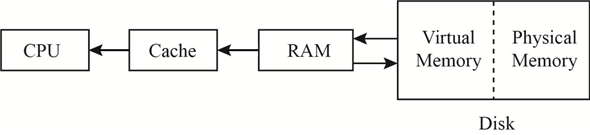
The virtual memory actually acts as a buffer RAM for the program process and makes space in RAM for other processes. This can be explained better as – suppose the user is having a 1080p full HD print for any movie in Blu Ray. User wants to watch the movie on the computer. The computer has 4 Gigabytes of RAM. The movie size on the Blu Ray is 64 Gigabytes.
Step-3
When the movie is played in the Windows Media Player, then a part of the RAM is allocated to the player to run the movie. If complete free RAM is allocated to the Media player, then there is no more space left for any other process to run.
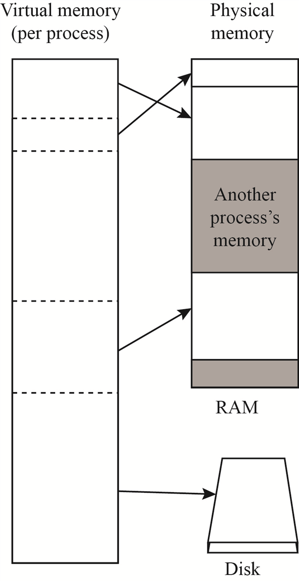
Smartly windows allocate space, known as Virtual Memory, in the hard disk drive which is used to provide the movie bits to the player, as memory-mapped files. This Virtual Memory also maintains threads linked to the original memory space where the file is stored, as local thread.
Step-4
The figure below shows how the virtual memory works.
Problem 13
Step-1
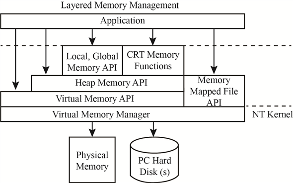
Different ways an application can use memory via the Windows32 API:
The Win32 API provides several ways for an application to use memory. They are
1. Virtual Memory
2. Memory-Mapping Files
3. Heaps
4. Thread-Local Storage
-
Virtual memory provides several functions like VirtualAlloc(), VirtualFree(), Virtual Lock(), SetProcessWorkingSetSize() that allow an application to reserve, release, to perform other memory operations and to specifying the virtual address at which the memory is allocated.
-
An application can use memory by Memory-Mapping a file address space, providing a means for two processes to share memory. It is a multistage process.
-
Applications can also use Heaps to use memory. If Win32 process is initialized, then it is created with a default heap. There are several functions like HeapCreate(), HeapAlloc(), etc., for heap-management in Win32 API. Private heaps can be created to provide regions of reserved address space for applications.
-
A thread-local storage mechanism provides a way for global and static data to work properly in a multithreaded environment. It provides both dynamic and static methods of creating thread-local storage. Thread-lock storage allocates global storage on a per-thread basis.
Problem 14
Step-1
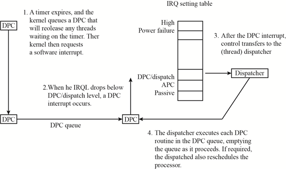
Deferred Procedure Calls
Every process executed in Windows 7 contains multiple threads to handle the program execution. The threads have multiple states of execution – Running, Runnable, Wait, Terminated, and Blocked.
Windows Kernel maintains a queue for both Asynchronous Procedure Call (APC) and Deferred Procedure Call (DPC). While a thread is in the running or runnable state then it is in queue for APC interrupts.
When a thread stops execution because either it has reached in the wait state or has terminated, the dispatcher is called by the kernel.
If within many layers of code, the thread enters the wait or terminated state, and it is found by the kernel that rescheduling of the process thread should take place, and then kernel calls the dispatcher requesting it to defer till the current process is completed, which triggers a DPC interrupt.
Whenever a deadlock state arises for a process making it “Not Responding,” then the windows Kernel uses the deferred procedure calls facility, to reschedule the process thread.
Step-2
The DPC states for execution are as shown in the figure below:
Problem 15
Step-1
Handles are a standardized interface to all kinds of objects. Like a file descriptor in UNIX, an object handle is an identifier unique to a process that confers the ability to access and manipulate a system resource. Handles can be duplicated within a process, or between processes. The latter case is used when creating child processes or implementing out-of-process execution contexts.
A process gets a handle by creating an object, by opening an existing object, by receiving a duplicated handle from another process, or by inheriting handle from a parent process, similar to the way a UNIX process gets a file descriptor. The object manager is the only entity that generates object handles.
Problem 16
Step-1
The design of Virtual Memory manager assumes that the underlying hardware supports virtual to physical mapping, a paging mechanism, and transparent cache coherence on multiprocessor systems and allows multiple page-table entries to map to the same physical page frame. The Virtual Memory Manager in Window XP uses a page – based management scheme with a page size of 4KB an IA32-compatible processor and 8KB on the IA64. The Windows XP VM manager uses a two-step process to allocate user memory. The first step reserves a portion of the process’s virtual address space. The second step commits the allocation by assigning virtual memory space. Windows XP limits the amount of virtual memory space a process consumes by enforcing a quota on committed memory.
For performance, VM Manager allows a privileged process to lock selected pages in physical memory, thus ensuring the pages are not paged out to the paging file.
Problem 17
Step-1
No-Access Page
The virtual memory manager in windows handles the memory locations, paging facility in windows, and the virtual address links for paging facility.
Some part of the memory is reserved for internal functions of the operating system. Remaining portion of the memory is free for applications which are executed on the system. The memory manager handles the links between the memory, virtual memory, and the physical memory.
Stacks are maintained to manage the locations allocated for the application memory, OS sector in the memory, virtual memory to manage the paging. If an application tries to access a memory link causing overflow condition in the stack, then the windows kernel triggers the no-access page facility.
No-access page facility is executed to prevent file from getting corrupt. The no access page facility is also used when connection to the external memory location is lost causing the virtual memory to trigger DPC which closes the application to release the memory – making it reusable.
Problem 18
Step-1
300-22-6E
Local Procedure Call (LPC) facility is used pass requests and result between client and server processes within a single machine. LPC is used to request service form the various Window XP subsystem. Three message-passing technique are.
1. Firstly, suitable for small message. In this case, port’s message queue is used as intermediate storage, and the message are copied from one process to other.
2. Secondly, for larger message. Here shared memory section object is created for the channel. Message set through the port’s message queue contains a pointer and size information referring to section object. This avoids the need to copy larger messages. The sender places data into the shared section and receive views them directly.
3. APIs are used, which reads and writes directly into a process’s address space.
When a client asks for a connection that uses window-manager messaging, the server sets up three objects:
1. a dedicated server thread to handle requests
2. a 64-KB section object
3. an event-pair object
The section object passes the messages, and the event-pair object performs synchronization.
Problem 19
Step-1
Cache Manager
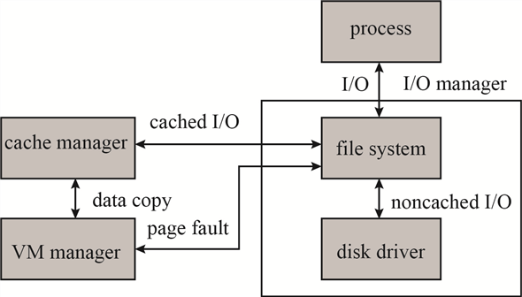
Windows manages cache memory and its working through a centralized facility known as Cache Manager, instead of a file system to maintain caching. All the components under the I/O Manager utilize the Cache Manager along with The Virtual Memory Manager to handle the flow of the process task.
The process flow between the I/O manager, VM manager, and Cache manager is as shown below:
Step-2
Step-3
Windows Cache Manager is based on caching files instead of caching raw memory blocks. The cache size is managed dynamically according to the free memory available. The files are mapped into Kernel Memory by the cache memory manager and a special interface is accessible to the Virtual Memory Manager for creating a private working set.
Each block of a cache is of 256KB, having its own virtual address control block (VACB). This VACB is used to store to file offset and the virtual address linked to the cache along with the count of processes using the cache block. Cache Manager maintains a dynamic array for handling VACB.
When a user level read request is sent to the I/O manager for a file, an IRP is send by the I/O manager to look, for the file residence volume, from the I/O Stack. Cache manager is called by the file system, if the requested file is marked as cacheable, to look for the data in cache file views. The entry for the file in the VACB array either provides the byte offset or returns invalid. A new memory block is reserved and an entry made in the VACB array if return value was invalid. The cache buffer is then used to make a copy of the data for the mapped file.
If frequent requests are made for the same data, then for such records the cache manager looks for access pattern. If a record is found in last three requests the data is pre-fetched before the next request for the same application/file is made. This saves the disk I/O to execute the cache process.
Problem 20
Step-1
300-22-10E
Every file in NTFs is described by one or more records in an array stored in a special file called the master file table (MFT). The MFT is located at the beginning of the partition. Normally MFT takes up 1 MB. The size of a record is determined when the file is created; it ranges from 1 to 4KB. Small attributes stored in MFT record itself are called resident attributes and large attributes stored in one or more contiguous extents on the disk are called non-resident attributes. Each file in an NTFS volume has a unique ID called a file reference. The file reference is a 64-bit quantity that consists of 48-bit file number and a 16-bit sequence number.
UNIX file system uses information nodes or inodes. Inode 0 contains the root of the file system. The file system is identified by the superblock which contains information about the layout of blocks, sectors, and cylinder groups on the file system. The inode does not contain a filename. Directory entry can point to the same node. A hard link makes it possible for file names to appear in several directories under several names.
Problem 21
Step-1
300-22-11E
A process is an executing instance of an application, and a thread is a unit of code that can be scheduled by operating system. Thus a process contains one or more threads. A process is started when some other process calls the create process routine. This routine loads any dynamic link libraries used by the process, and creates a primary thread.
The windows XP process manager provides services for creating, deleting, and using processes, threads, and jobs. CreateProcess() in the original process calls an API in the process manager to actually create the process. Once a new process is created, the initial thread is created, and an asynchronous procedure call is delivered to the thread to prompt to prompt the start of execution at user-mode image loader. The loader is link library which is automatically mapped into every newly created process.
The process manager also implements the queuing and delivery of asynchronous procedure calls to threads.
Problem 22
Step-1
Fiber and Thread Abstraction
Whenever a process is created for the execution of an application or a program, a thread or multiple threads (depending on the application requirement) are created for providing required resources to the application and Operating system and enabling proper management of the process, involving memory, resources and I/O.
Fiber is similar to a thread. It also helps in linking process with the resources and memory management.
The Fiber/threads are managed by the Memory manager and directly linked with the process termination. If a process is terminated without completing the task, then the fiber/threads which are linked with the process are also terminated auto. In windows 7 the user can view the count of threads working for a specific process using the Resource Monitor but cannot close a thread. As both threads and fibers used by a process are not available to the user they are termed as abstract.
Step-2
Fiber and thread differ only in the scheduling styles. The threads use the preemptive scheduling mechanism and are implicit in style. The fibers use non-preemptive scheduling and are explicit in style. This difference results in giving kernel or the manager better control. Threads can be interrupted by the kernel or the program process while it is still in the running mode. Fibers can only be interrupted by the program process giving protection to the critical sections of the code running.
Advantage of thread is that it prevents other threads to execute if one (of many) finds that the computation is not resulting in any yield required for process continuation. This makes a thread lighter and prevents CPU cycles wasted in processing the thread.
Multiple threads can run on multiple cores at the same time whereas fiber does no execute parallel. Only one fiber for a process section is executed at given point of time.
Problem 23
Step-1
User-Mode Scheduling (UMS) Vs Fibers
User-mode scheduling (UMS) is a new mechanism given in windows 7 to overcome limitations of fibers. Fibers are similar to threads and are used to create sub-links for data/resources needed during the execution of a process. Problems with fibers is that unlike threads they do not have their own Thread Environment Block(TEB).
When a fiber is running the process, then the fiber block is executed in the kernel and kernel handles it through kernel dispatcher, forcing the CPU to lose control till dispatcher sets it free. More problems arise when fiber changes the priority for any thread in the kernel or if any asynchronous Input Output request is generated by the fiber.
To overcome the problems of fibers, UMS provided an alternate. In UMS windows thread is not just one thread but are two threads. First thread is known as the kernel thread (KT) and the second thread is called user thread (UT). Both KT and UT maintain different stacks for themselves. The TEB of each UT is used by the UMS to identify them uniquely.
When a UT enters the kernel, an explicit switch is made to the KT that corresponds to the UT identified by the current TEB. The reason the kernel does not know which UT is running is that UTs can invoke a user-mode scheduler, as fibers do. But in UMS, the scheduler switches UTs, including switching the TEBs.
The UT is not accessible to the programmer directly. The KT gets blocked when its corresponding UT enters the kernel for execution. When UT enters the kernel, the kernel is switched to the scheduling thread known as primary thread. This primary thread is used by the UML to pick other UT to be executed. Once KT operation is completed, it returns the control to the user mode.
Step-2
The only trade-offs between fibers and UMS is that; Fibers can be used directly by the programmer for their application whereas UMS is not accessible to the programmer.
Problem 24
Step-1
User thread and kernel thread
User-mode scheduling (UMS) is a new mechanism given in windows 7 to overcome limitations of fibers. To overcome the problems of fibers, UMS provided an alternate. In UMS windows thread is not just one thread but are two threads. First thread is known as the kernel thread (KT) and the second thread is called user thread (UT). Both KT and UT maintain different stacks for themselves. The TEB of each UT is used by the UMS to identify them uniquely.
When a UT enters the kernel, an explicit switch is made to the KT that corresponds to the UT identified by the current TEB. The reason the kernel does not know which UT is running is that UTs can invoke a user-mode scheduler, as fibers do. But in UMS, the scheduler switches UTs, including switching the TEBs.
The UT is not accessible to the programmer directly. The KT gets blocked when its corresponding UT enters the kernel for execution. When UT enters the kernel, the kernel is switched to the scheduling thread known as primary thread. This primary thread is used by the UML to pick other UT to be executed. Once KT operation is completed, it returns the control to the user mode.
Problem 25
Step-1
KTs and UTs
Kernel Thread (KT) is also known as Light Weight Process (LWP). Kernel creates and schedules the KT. User Thread (UT) is not as expensive to create and to manage as KT. Creating KT is handled by the Kernel and is platform specific.
The threading library creates the User Thread and schedules the calling of the thread as per the application inheriting the threading library. User Thread runs only in the user mode. When a process is executed by the user, then its corresponding user threads are created. User threads are portable in nature as they are user specific and handled by the user application.
Step-2
If the CPU is having single processor or uniprocessor system, then both User thread and Kernel Thread are executed and managed by respective originator. If the CPU has more than one processor, that is its using multiprocessor system, then a performance issue is seen due to handling of the threads.
Different Kernel Threads can be executed on different CPU’s as they are handled by the Kernel Scheduler. The User Thread, handled by the threading library can run on one processor but not on multiprocessor (that is they cannot be executed on parallel cores of the processor).
Step-3
To manage the execution of User Threads different implementation models are as followed:
-
Many-to-One: In many-to-one threading model, various User Threads are linked to One Kernel thread for implementation on parallel processor.
-
One-To-One: In One-to-One threading model, Kernel Thread is linked with the User Thread directly. In this each KT is treated as a Virtual Process (VP). The Kernel Scheduler manages the VP.
Problem 26
Step-1
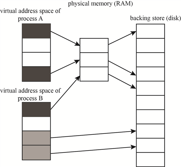
Virtual Address Space
In Operating system the virtual memory manager, maintains the flow of process and handles the interrupts; swapping memory between different I/O units. When a process is executed; the application is occupied in the hard disk space, from where it starts execution. The execution takes place in the RAM. From RAM the data and control is transferred as per the need of the process.
Step-2
The flow of the process is shown in the diagram below:
Step-3
The allocation of the virtual memory is managed by the windows VM manager in two simple steps:
1. Step one block the space (pages) in the virtual address space of the process.
2. Step two confirms the allocation by assigning virtual memory space. This virtual memory space can be either the physical memory or the space in the paging file.
Step-4
The memory layout for a windows process is shown in the figure below:
Step-5
When paging is done for a process, it is allocated a limited space from the virtual memory. This allocation of the virtual memory is dependent on the processor type. The VM manager maintains the flow from virtual memory to the process and to the physical memory. This process has to be constantly maintained. The page table maintained by the VM manager is used to store the process ID, the link of the virtual address, the address at the physical memory. This page table has the entire flow requirement for the process and the memory addresses.
When process is having high priority, then instead of expanding the allocation of the virtual memory, the link addresses in the page table are increased, which increases the use of virtual address space but not the virtual memory.
Step-6
The page table relation between the virtual memory and the main memory is as given below:
Problem 27
Step-1
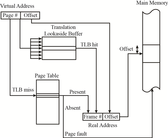
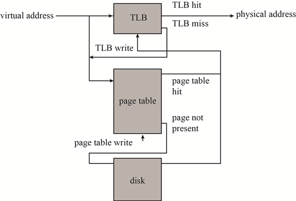
Page Table Pages
The most recently used mappings are stored in a cache memory managed by the Memory management (VM manager). This cache block of memory is known as Translation Lookaside Buffer (TLB). TBL is also known as the associative cache memory block.
The TLB is first searched when a translation is needed for the virtual address to physical address. When a value is found in the TLB, the corresponding physical address is returned and the link is transferred to the physical address. If the value is not found in the TLB the link is searched for the mapping address in the page table. If value exists in the page table then it is written in the TLB.
Step-2
Hence using TLB the VM manager maintains the page table and the virtual memory. The figure shown below shows the control flow for TLB and the Page table.
Step-3
The active pages of the page table are stored in the RAM, whereas the inactive block of pages is still stored on the hard disk of the system.
Problem 28
Step-1
Windows system hibernate
In windows operating system Hibernation is an option available to the user as a substitute to sleep mode. In sleep mode the computer stores the current state of the active tasks and unsaved documents in RAM. It consumes a unit of power to maintain this storage in the memory.
In Hibernation mode, the current state of the active tasks and the unsaved documents are stored in the physical memory. System can be powered off after hibernation without losing on the state of the tasks or the unsaved data.
When system is powered on, it checks for the Hiberfil.sys which has the settings for the hibernation state and pagefile.sys which stores the state of the process tasks and the unsaved data.
A powered off system after hibernation is equivalent to a powered off system without hibernation. In a normal system, when it is turned off, RAM can be replaced without causing any change in the booting process after replacement; except for the performance speed depending on the type and size of RAM installed. Similarly, we can even replace the processor in a normal system when it is turned off; without affecting the windows booting process (except for the device drivers needed, if any) or the data stored. The only change seen is in the BIOS settings which will update the list of devices attached.
Step-2
These days’ external storage devices are used to boot the computer. These devices provide the space not only for the data, but also for the Operating system. System is turned power off after hibernate state saved in the external storage device and RAM + CPU changed while the system is powered off. As this external storage device was not even connected to the system while changes were made, hence no change in the files takes place. Upon starting of the system, the bios will look for any change in the hardware and will update the settings. The process states saved are independent of the CPU on which they are working or the RAM size.
Hence after rebooting, post BIOS update, the system will regain itself from the hibernation state, affecting only the performance speed depending on the processor power and RAM type + size.
Problem 29
Step-1
Threads Suspend Count
Each process has multiple threads involved with it to handle the flow for the desired output. Windows associates suspend count to each thread created. The initial value of suspend count for each thread is zero. Based on the value of suspend count a thread is either executed or left in suspended mode. The thread having suspend count zero or less are executed or to be executed. If the thread has a suspend count above zero then it is left without execution.
Step-2
The debugger, when attached to process, increases the suspend count for process threads by one. When a process ends and is detached from the debugger, suspend count is reduced by one. While the process is in the execution state, the suspend count of threads is temporarily reduced by one.
Step-3
The suspend count for threads is used in windows while switching between processes executing multitasking. Suppose two different processes ‘A’ and ‘B’ received together for processing. To implement multi-tasking both processes should be executed together – switching between the two.
When thread of process ‘A’ are executing the count for them becomes greater than zero, while for the threads of process ‘B’ are less than or equal to zero. So, the task is switched to process ‘B’ making the value of its threads greater than zero and threads of process ‘A’ are reduced back to zero.
This way, the both the processes get time for execution, and multitasking is implemented.