Problem 1
Step-1
Dead lock in real life
When the resources are not shared among people or processes, the situation is known as dead lock. The three examples to show the deadlock condition in the real life are as given below:
1. When two cars are trying to cross the same one lane bridge from the opposite ways, the deadlock condition occurs.
2. When two trains are trying to cross the same one lane bridge on single track from the opposite ways, the deadlock condition occurs.
3. When two people are playing a game of baseball and one of them has the bat while the other holds the ball. In this situation, if the resources are not shared, the game cannot be played and a deadlock occurs.
Problem 2
Step-1
Unsafe state:
Unsafe state is the situation that happens when the system contains less available resources but guarantees the completion of at least one job running on the system. But this may lead to a deadlock problem.
Deadlock:
In a computer system, a set of blocked processes each holding a resource and it is waiting to acquire the resource held by another process in the set is called a deadlock problem.
Step-2
Example:
Consider that the system with 15 devices of same type and it is in an unsafe state.
| Job Number | Device allocated | Maximum required | Remaining needs |
|---|---|---|---|
| 1 | 5 | 9 | 4 |
| 2 | 3 | 7 | 4 |
| 3 | 4 | 8 | 4 |
From the table,
• The total number of devices allocated to the system is “12” and the total number of available devices is “15”.
• The remaining devices which are available idle in the system is “3”  .
.
• This proves that the system is in unsafe state. Because, the number of available devices is “3” and it is less than the number needed to satisfy the maximum requests “4”.
• So, none of the job completes its execution and it suffers from the problem of deadlock.
• But there is way to turn the system into a safe state,
o The way is that to put the Job number “2” into the execution and it will face the execution time problem (for example: “division by zero” problem) and it will be terminated after some period of time by releasing 3 allocated devices.
o Now, the system turns into safe state and it uses the released resources of “job2” to complete the execution of “job1” and “job3”.
Therefore, the system in an unsafe sate is not necessarily deadlocked.
Problem 3
Step-1
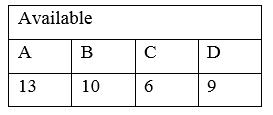
Allocation Max Available
A B C D A B C D A B C D
P0 0 0 1 2 0 0 1 2 1 5 2 0
P1 1 0 0 0 1 7 5 0
P2 1 3 5 4 2 3 5 6
P3 0 6 3 2 0 6 5 2
P4 0 0 1 4 0 6 5 6
Step-2
a)

A B C D
P0 0 0 0 0
P1 0 7 5 0
P2 1 0 0 2
P3 0 0 2 0
P4 0 6 4 2
Step-3
b)
The available matrix is [1 5 2 0]. So, the safety sequence occurs when the criteria Need⇐ Available is satisfied. From the Need matrix calculated above, the process  does not require any resources. Also, the need matrix of
  is less than the available matrix.
Step-4
So, take the process  and calculate [Available] = [Available]+[Allocation(
 )], so Available = [1 5 2 0] + [0 0 1 2] = [1 5 3 2].
Next, take the process  and update the available matrix as: [1 5 3 2] + [1 3 5 4] = [2 8 8 6].
Step-5
Now, the need matrix of process  is less than the available matrix, so calculate the available matrix as: [2 8 8 6] + [0 6 3 2] = [2 14 11 8].
Step-6
Next, the need matrix of process  is less than the available matrix, so calculate the available matrix as: [2 14 11 8] + [0 0 1 4] = [2 14 12 12].
Step-7
In the last step, the process  is taken, and its need matrix is less than the available matrix, so calculate the available matrix as: [2 14 12 12] + [1 0 0 0] = [3 14 12 12].
Step-8
So, the system is in a safe state and the safe sequence is 
Step-9
c)
When request (0, 4, 2, 0) arrives from P1, first the Banker’s algorithm checks whether request  Available, since (0, 4, 2, 0) < (1, 5, 2, 0) algorithm pretends, that this request can been fulfilled and arrived at new state.

Allocation Max Need Available
Process A B C D A B C D A B C D A B C D
P0 0 0 1 2 0 0 1 2 0 0 0 0 1 1 0 0
P2 1 3 5 4 2 3 5 6 1 0 0 2 2 4 6 6
P3 0 6 3 2 0 6 5 2 0 0 2 0 2 10 9 8
P1 0 4 2 0 1 7 5 0 0 3 3 0 3 14 11 8
P4 0 0 1 4 0 6 5 6 0 6 4 2
At this state after executing safety algorithm, one of the ordering (P0, P2, P3, P1, and P4) satisfies the safety requirements.
Note: The other ordering of the process can be (P0, P2, P1, P3, and P4), (P0, P2, P1, P4, and P3) until and unless there is no possibility of deadlocks.
Hence, request can be granted immediately to process P 1. ****
Problem 4
Step-1
One way to ensure that circular wait should hold is to impose a total ordering of all resources types and to require that each process request resource in an increasing order of enumeration.
Let R= {R1, R2, … ,Rm} be the set of resource types. Each resource type is assigned a unique number which is of type integer. It allows us to compare two resources and to determine whether one precedes another in our ordering.
 is one-to-one function, N is a set of natural numbers.
To have no circular wait.
One must have 

By the transitivity rule 
is impossible. Hence no circular wait. But in containment. Whenever a thread acquire the lock for object A,B, C, D, E it must first acquire lock for another object F.
 is in deadlock.
 not in deadlock.
i.e. if any two thread will be in dead lock than sixth thread will be in to avoid the dead lock. That is object F can occur and be acquiring a lock whenever a deadlock is to occur.
Problem 5
Step-1
Banker Algorithm
The given code segment implements the banker’s algorithm. In the given code segment, two for loos are executed as the outer for() loops for n number of times which makes the run time to  .
.
There are two if() conditions given in the code segment and a for loop which will be executed till m times. So, in this case the collective run time will be  .
.
In the worst case if both the conditions are satisfied, the for() loop will be executed till  times and
  represents m run time. Thus in any case the run time of the code segment will be
  .
.
Problem 6
Step-1
2481-7-12E SA: 8683
SR: 6376
a)
The arguments in favour of installing the deadlock-avoidance algorithm are:
1. It avoids deadlocks and the costs incurred by rerunning the terminated jobs.
2. Reduces the wastage of resources by rerunning the jobs and also saves the time to run the aborted processes all over again.
3. Resource utilization will be maximized and the machine idle-time is reduced.
Step-2
b)
The arguments against installing the deadlock avoidance algorithm are:
1. The average execution time per job will be increased by about 10 percent.
2. The turnaround time would increase by about 20 percent. It introduces an overhead on the execution
3. Deadlocks occur about twice per month and they cost little than the overhead added by installing the deadlock avoidance algorithm.
Problem 7
Step-1
Detection of starving processes
No, the detection of the starve process is very difficult. A process is said to be starve process, if the process is never be executed. If a process is waiting for a long time for the requested resources, and the time is beyond the response time, than, the process is said to be starving. As the response time for any process is increased, the probability of starving is increased.
The system can calculate the response time T to identify the problem of starvation. The resources can be allocated to a fix time interval. The system must have to fix the time T for any process P for execution. In any condition, the response time should not be delayed. By doing so, the system can deal with the problem of starving.
Problem 8
Step-1
2481-7-7E SA: 8683
SR: 6376
a)
Deadlock will not occur. By the given resource allocation policy, the necessary condition that cannot occur is the No Preemption condition. No preemption states that resources cannot be preempted, that is, a resource can be released only voluntarily by the process holding it, after that process has completed its task. But here, if blocked process has desired resource, then these resources are taken away from it and are given to the requesting process. So, it is not holding no preemption condition.
Step-2
b)
Indefinite blocking can occur. Because, processes might continuously come and take resources from the blocked process (as P2 gets resources from the blocked process P0); the blocked process might not get a chance to fulfill its needs.
Problem 9
Step-1
Deadlock detection
Yes , the deadlock detection can be implemented with the help of safety algorithm. The value of Max is representing a process which is requested maximum time and Max is a vector. The value if  represent the resources for any process.
In the calculation of safety algorithm, Need matrix is required. The Need matrix represents

Thus,

It is given that Waiting matrix is playing the same role as played by the Need matrix. So, it can be said that

So, the deadlock detection can be implemented with the help of safety algorithm.
Problem 10
Step-1
2481-7-16E SA: 8683
SR: 6376
There are four conditions that must be hold for a deadlock to occur.
1. Mutual exclusion
2. Hold and Wait
3. No pre-emption
4. Circular wait
Circular-wait occurs only when there are a set of processes where, one process is waiting for the resources of another process. There must be atleast more than one process. With a single process, the circular wait condition does not hold. So it is not possible to have a deadlock involving only one process.
Problem 11
Step-1
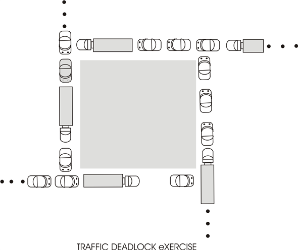
a. The four necessary conditions for deadlock hold in this example for the following reasons: (i) Mutual Exclusion: Each of the vehicles present in the streets hold a non-sharable resource: the part of the road they occupy, which they cannot share with the other vehicles.
Step-2
(ii) Hold and Wait: Each of the vehicles hold the space resource they occupy and are waiting the space in front of them to be freed by other waiting vehicles.
Step-3
(iii) No Preemption: There is no possibility of preemption as none of the vehicles can give up their resource. In this situation preemption would have to take the form of a vehicle pulling into a parking lot, or a crane reaching down and lifting a vehicle off the road.
Step-4
(iv) Circular Wait: Circular wait is present because each vehicle is waiting for the space in front of it, and some vehicles occupy spaces where two vehicles wait on them. It is thus possible to trace a cycle of waiting cars. This is the weakest assertion in the set, though, and is clearly untrue out at the edges somewhere, since some car can clearly move someplace in the city. If you have ever experienced grid-lock, though you know that this is small comfort, and that a rule to avoid even “local” deadlock is extremely desirable.
Step-5
b. The simple rule that could be used to avoid traffic deadlocks in such a system is that intersections should always remain clear as lights change. In this way, the resource of space in the intersection is freed for use at periodic intervals (light changes).
Problem 12
Step-1
Deadlock is a condition where a process enters a never ending wait situation and hence the execution is halted for uncertain time duration.
The major drawback of a process entering deadlock situation is, the resources the process was using at the time of deadlock arrival gets occupied until and unless the process wakes up from deadlock and finishes execution.
Discussing the four necessary conditions of deadlock for this multi-threaded system; the reader-writer locks may contribute in the way discussed below:-
• As there are several reader-writer locks, mutual exclusion is achieved successfully.
• Each thread can hold one reader and writer, while keep waiting for another lock. Hence, hold-and-wait condition is also possible.
• No reader-writer lock is available for taking away hence, preemption is not possible.
• As multiple threads may wait for a reader-writer lock already acquired by some other thread in the process; process may go into a circular wait condition.
If a multi-threaded application uses several reader-writer locks, the deadlock is more likely to arrive. Hence, the answer is YES a deadlock arrives in such situation.
Problem 13
Step-1
Refer to the code provided in Figure 7.4 of chapter 7 of the textbook for complete code.
Step-2
Occurrence of deadlock by the CPU scheduler: There are four necessary conditions that must hold for a deadlock to occur. They are as follows:
• Mutual exclusion – At least one resource must be in non-shareable mode.
• No-preemption – The resources can only be released voluntarily by the process.
• Hold and wait – A process must be holding at least 1 resource and should be waiting for another resource held by another process.
• Circular wait – In a set of processes {P1, P2…..Pn} there must exist waiting between them such that process P1 is waiting for the resource held by process P2 and so on.
Step-3
The function of CPU schedular is to select the process ready to execute and allocate them CPU.
The code given in Figure 7.4 uses two thread requesting for same process “first_mutex” and “second_mutex” but in different order. The work of CPU scheduler here is to provide CPU to the process which is ready for execution.
• Suppose, there is a situation that in do_work_one function, only one statement that is first_mutex, gets acquired but second_mutex is not acquired by do_work_one function.
• Now, after acquiring of the first_mutex CPU scheduler will give control to do_work_two function. In do_work_two function the first statement gets executed and it is seen that the second_mutex is not acquired at the moment. So, do_work_two function acquired the second_mutex.
• Now, when second statement of any function gets executed, then the statement needs to wait for the other mutex.
• This is because second statement of do_work_one function requires second_mutex which is currently held by do_work_two function.
• Similarly, second statement of do_work_two function requires first_mutex which is being held by do_work_one function.
• In this way, both of the functions enters the waiting state and deadlock occurs.
Step-4
Contribution of CPU scheduler for deadlock:
• The role of CPU scheduler in the given program is to provide CPU to the thread that is ready for execution.
• A CPU scheduler uses many algorithms to do so like giving fix time slot to a thread (pre-emption).
• Suppose, there is a situation that in do_work_one function, the first statement gets executed and the CPU scheduler gives the CPU time to do_work_two function.
• The do_work_two function will hold second_mutex while waiting for first_mutex while the do_work_one function is holding the first_mutex and waiting for second_mutex to be free.
• In this case, there will be a deadlock as both the threads are holding a mutex and requesting for another mutex.
Hence, this way CPU scheduler can contribute in deadlock process.
Problem 14
Step-1
Function to fix deadlock:
The deadlock condition can be prevented by adding a new lock named as lock3. This is acquired before the two locks are acquired.
The transaction function to prevent the deadlock condition is as given below:
Step-2
void transaction(Account from, Account to, double amount)
{
Semaphore lock1, lock2, lock3;
//acquire the lock3
Wait(lock3);
// request to get the lock for lock1
lock1 = getLock(from);
// request to get the lock for lock2
lock2 = getLock(to);
// acquire the lock to perform the transaction
wait(lock1);
// acquire the lock to perform the transaction
wait(lock2);
// The first lock is used to withdraw the balance from any account and the second lock is used to deposit the balance in an account.
// withdraw the balance from the account
withdraw(from, amount);
// deposit the balance to the account
deposit(to, amount);
//After performing the transactions, both the locks is released by using signal parameter to prevent the deadlock condition.
// first release the lock 3
signal(lock3);
// release the lock2 and lock1 after performing transaction
signal (lock2);
signal(lock1);
}
Problem 15
Step-1
a.
Runtime overheads:
• The algorithm in which it is less efficient the resource allocation graph scheme is said to be known as banker’s algorithm. It is one of the algorithms of deadlock-avoidance schemes.
• The runtime overheads get increased by the deadlock avoidance such that it is only because of the current resource allocation cost.
Step-2
b.
System throughput:
• The request should be given by the process to use the resource such that after completion of using it, the resource must be released by the process.
• For the prevention of deadlock, the deadlock avoidance scheme will allow a number of resources for concurrent use than schemes.
• Finally, the system throughput will get increased by the deadlock avoidance scheme.
Problem 16
Step-1
In the banker’s algorithm, a process must not request a maximum number of instances of each resource type than the number of resources available in the system. This algorithm allocates the requested number of resources to the process only if the system remains in a safe state. Otherwise, it does not allocate the requested number of resources to the process to avoid deadlock. Then the process must wait until the resource available.
• Available and Max are the data structures of the banker’s algorithm.
• The Available is a vector contains m number of available resources of each resource type for n number of processes.
• The Max indicates the maximum number of demands of each process for each resource types.
Step-2
a. Increase Available:
• If the Available length increased, then the number of available resources of each resource type will increase.
• Then the instances of each resource type of a process will increases. The process can request for more instances of each available resource type.
• This change can be made safely without deadlock.
Step-3
b. Decrease Available:
• If the Available length decreased, then the number of available resources of each resource type will decrease. The resource will permanently remove from the system.
• Then the instances of each resource type of a process will decrease. The process cannot request more instances of each available resource type.
• If the process requests the number of instances of each resource type than the number of resources available in the system, then the deadlock will occur.
• This change may lead to deadlock.
Step-4
c. Increase Max for one process:
• If the Max increased for one process, the number of demands of the process will increase. The process can demand for more resources than allowed.
• If the process requests more instances of a resource than the available resources of each type, then the process must wait until another process release that resource.
• If another process does not release the resource, then this condition leads to deadlock and system will be in the unsafe state.
Step-5
d. Decrease Max for one process:
• If the Max decreased for one process, the number of demands of the process will decrease. The process cannot demand more resources than allowed.
• If the process requests fewer instances of a resource than the available resources of each type, then the process must not wait until another process release that resource.
• This condition does not lead to deadlock and system will be in the safe state.
Step-6
e. Increase the number of processes:
• If the number of processes increases in the system, the resource allocation will be difficult.
• If two or more processes requests for same instances of a resource at the same time, then some of the processes must wait until the resource is available.
• This condition has the possibility of deadlock. The system will be in an unsafe state.
Step-7
f. Decrease the number of processes:
• If the number of processes decreases in the system, the resource allocation will be easier.
• If the number of processes is less than the number of resources available in the system, then the system remains in a safe state.
Problem 17
Step-1
When there are 4 resources to be shared among 3 processes, and one process can occupy at most 2 resources, the system will be deadlock free. It has been explained through following points:
• Two processes will hold 2 resources (1 each).
• Third process will occupy 2 resources.
• Third process can’t hold more than this, hence, it can release these resources after use.
• When any of the 2 or both process will be released by third process, other process will be able to hold the free resource.
Step-2
The situation can be better understood by the diagram given below:
In figure 1 all the resources R1, R2, R3, and R4 have been allocated among 3 processes P1, P2 and P3.
R1 has been allocated to P1.
R2 has been allocated to P2.
R3, R4 has been allocated to P3.
P3 has occupied the maximum number of resources it can hold; hence, it is not waiting any other process to release resource. It will first release the resource, then only will occupy any other resource.
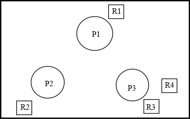
Figure 1
Now when P3 has released R3 as shown in Figure 2 but still holding R4. R3 now can be allocated to any of the process.
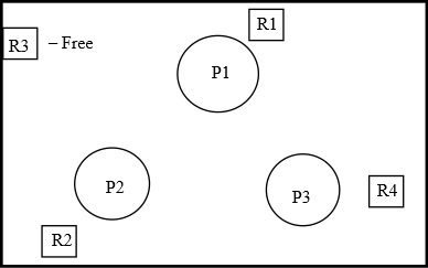
Figure 2
In figure 3, R3 has been allocated to P2. Hence, P2 has 2 resources R2 and R3.
R1 has been allocated to P1.
R4 has been allocated to P3.
This diagrammatic explanation proves that it is not a deadlock situation.
Problem 18
Step-1
Proof using contradiction to show the system is deadlock free if the following two conditions hold:
Condition 1: The max need of each process is between 1 and  resources.
Condition 2: The sum of all max needs is less than  .
.
Let, the system is not deadlock free.
If there is deadlock in the system, then the sum of all allocations of processes is equal to the number of resources.
That is,  .
.
This is because only one type of resource is present, and a process can request or release only one resource at a time.
From condition 2, The sum of all max needs is less than  . That is,

Therefore,  . That is, the sum of all needs of processes is less than the number of resources. Then, the need of at least one process is 1. That is
  . This condition shows that there is no deadlock.
Step-2
Form condition 1, the maximum need of each process is between 1 and  resources. That is, a process can release at least one resource. Then, the
  resources of same type can be shared by
 processes.
Here, the two conditions satisfy the deadlock free condition.
Therefore, the system that holds the two conditions is deadlock free.
Problem 19
Step-1
Use the following rule to perform the dining-philosophers problem without causing deadlock.
When a philosopher makes a request for the chopstick, there are three situations:
1. If there are no chopsticks, the request cannot be accepted and philosopher should wait until the availability of chopsticks.
2. If there is one chopstick, the request cannot be satisfied until there are two chopsticks available.
3. If there are two chopsticks available, the request can be accepted and philosopher can eat.
Step-2
Algorithm :
do
{
Think
if(chopstick[i]&& chopstick [i+1])
{
pickup(chopstick [i], chopstick [i+1 mod 5]);
Eat;
putdown(chopstick [i], chopstick [i+1 mod 5])
}
else
{
wait(chop stick [i]);
wait(chopstick [(i+1)%5])
}
}while(true);
Problem 20
Step-1
Use the following rule to perform the dining-philosopher’s problem:
When a philosopher makes a request for the chopstick, there are three situations:
1. If there are no chopsticks, the request cannot be accepted and philosopher should wait until the availability of chopsticks.
2. If there is one chopstick, the request cannot be satisfied until there are three chopsticks available.
3. If there are two chopsticks, the request cannot be satisfied until there are three chopsticks available.
4. If there are three chopsticks available, the request can be accepted and philosopher can eat.
Step-2
Algorithm:
do
{
state[i]=Thinking;
state[i] = hungry;
if(chopstick[i]&& chopstick[i+1]&& chopstick[i+2])
{
pickup(chopstick[i],chopstick[i+1],chopstick[i+2mod 5]);
Eat;
pickdown(chopstick[i],chopstick[i+1],chopstick[i+2mod 5]);
}
else
{
wait(chopstick[i]);
wait(chopstick[i+1]);
wait(chopstick[(i+2)%5]);
}
}while(true)
Step-3
Explanation :
• At the start, start do-while loop means each state will be verified.
• At the first philosopher think, whether he is going to eat or not.
• Check whether three chopsticks are available or not. If yes, then,pickup the chopstick and start eating.
• Else wait for the chopsticks until Philosopher get all the three chopsticks.
Problem 21
Step-1
Consider that a system is using two resources R1 and R2 and there are three processes P1, P2 and P3. The resources will be allocated to the processes based upon the requirements.
The allocation status of the two resources R1 and R2 for the processes P1, P2 and P3 are as follows:
R1R2R1R2
Consider the following:

Step-2
If the process P2 were to make a request with (1, 0), then the system will allow it because the processes can complete in the sequence as follows:

If the process P2 were to make a request with (0, 1), then the system will allow it and the processes can complete in the sequence as follows:

Step-3
But, if the process P2 were to make a request with (1, 1), then the request will get rejected as no process can satisfy the request. Hence no process will be able to complete.
Problem 22
Step-1
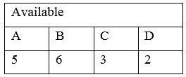
Determination or safe or unsafe states:
In the Banker’s algorithm, four types of matrices are used. Those are,
1. Available: An m length vector representing the number of available instances of any resource at a time.
2. Max: This is an n to m matrix (n specifying different processes). Each entry implies the maximum instances of a resource type that can be requested by a particular process.
3. Allocation: This is also an n to m matrix. Each entry specifies instances of a resource held by a particular process at a time.
4. Need: An n to m matrix. Each entry in this matrix implies the number of instances of a resource needed by a particular process at a time. According to safety algorithm, Need = Max – Allocation
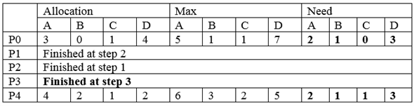
The snapshot of the system and Need matrix is,
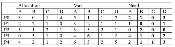
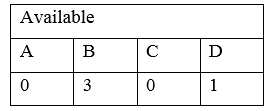
The available matrix is,
Step 1:
As, Need of P2 is less than Available, the requirements of P2 can be fulfilled with the available resources and P2 will be completed. After completion, it will release all resources to the Available pool.
So, the current snapshot of the system is,
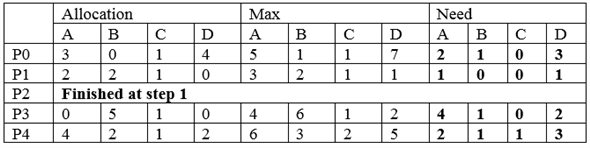
And,
Step 2:
Now, Need of P1 is less than Available, the requirements of P1 can be fulfilled with the available resources and P1 will be completed. After completion, it will release all resources to the Available pool.
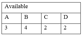
So, the current snapshot of the system is,
And,
Step 3:
Now, Need of P3 is less than Available, the requirements of P3 can be fulfilled with the available resources and P3 will be completed. After completion, it will release all resources to the Available pool.
So, the current snapshot of the system is,
Step-2
And,
Step-3
Step 4:
Now, Need of P0 and P4, both are greater than the Available matrix. So, neither of those will be catered with the current available resources.
So, the algorithm will stop and there is no safe sequence in this case. So the state is unsafe.
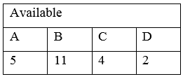
Step-4
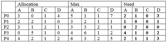
The snapshot of the system and Need matrix is,
The available matrix is,

So, according to safety algorithm,
Step 1:
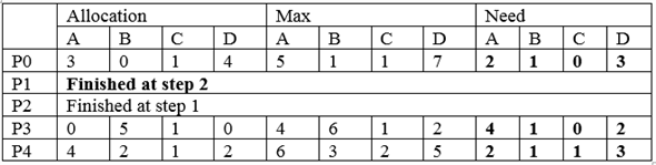
As, Need of P1 is less than Available, the requirements of P1 can be fulfilled with the available resources and P1 will be completed. After completion, it will release all resources to the Available pool.
So, the current snapshot of the system is,
And,
Step-5
Step 2:
Now, Need of P2 is less than Available, the requirements of P2 can be fulfilled with the available resources and P2 will be completed. After completion, it will release all resources to the Available pool.
So, the current snapshot of the system is,
And,
Step 3:
Now, Need of P3 is less than Available, the requirements of P3 can be fulfilled with the available resources and P3 will be completed. After completion, it will release all resources to the Available pool.
So, the current snapshot of the system is,
And,
Step-6
Step 4 :
Now, Need of P4 is less than Available, the requirements of P4 can be fulfilled with the available resources and P4 will be completed. After completion, it will release all resources to the Available pool.
So, the current snapshot of the system is,
And,

Step-7
Step 5:
Now, Need of P0 is less than Available, the requirements of P0 can be fulfilled with the available resources and P0 will be completed. After completion, it will release all resources to the Available pool. And all processes will be completed without any deadlock. So the state is safe and the safe sequence will be the sequence of completion of the processes.
So, the current snapshot of the system is,
And,
Therefore, the safe sequence is P1 P2 P3 P4 P0.
Problem 23
Step-1
Illustration of safe state:
In the Banker’s algorithm, four types of matrices are used. Those are:
1. Available**:** An m length vector representing the number of available instances of any resource at a time.
2. Max**:** This is an n to m matrix (n specifying different processes). Each entry implies the maximum instances of a resource type that can be requested by a particular process.
3. Allocation**:** This is also an n to m matrix. Each entry specifies instances of a resource held by a particular process at a time.
4. Need**:** An n to m matrix. Each entry in this matrix implies the number of instances of a resource needed by a particular process at a time. According to safety algorithm, Need = Max – Allocation
The snapshot of the system and Need matrix is,
| Allocation | Max | Need
---|---|---|---
| A | B | C | D | A | B | C | D | A | B | C | D
P0 | 2 | 0 | 0 | 1 | 4 | 2 | 1 | 2 | 2 | 2 | 1 | 1
P1 | 3 | 1 | 2 | 1 | 5 | 2 | 5 | 2 | 2 | 1 | 3 | 1
P2 | 2 | 1 | 0 | 3 | 2 | 3 | 1 | 6 | 0 | 2 | 1 | 3
P3 | 1 | 3 | 1 | 2 | 1 | 4 | 2 | 4 | 0 | 1 | 1 | 2
P4 | 1 | 4 | 3 | 2 | 3 | 6 | 6 | 5 | 2 | 2 | 3 | 3
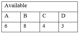
The Availability matrix is,
Available
A | B | C | D
3 | 3 | 2 | 1
Step 1:
According to safety algorithm, Work = Available.
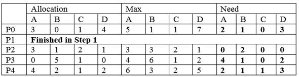
The Need for P0 is less than Work (2 ⇐ 3, 2 ⇐ 3, 1⇐ 2 and 1 ⇐ 1), so, P0 will be allocated the needed resources and will be finished. After finishing of P0, all allocated resources of it will be added to the Work matrix. So, Work = Work + Allocated[i].
The updated matrices are:
| Allocation | Max | Need
---|---|---|---
| A | B | C | D | A | B | C | D | A | B | C | D
P0 | Finished in step 1
P1 | 3 | 1 | 2 | 1 | 5 | 2 | 5 | 2 | 2 | 1 | 3 | 1
P2 | 2 | 1 | 0 | 3 | 2 | 3 | 1 | 6 | 0 | 2 | 1 | 3
P3 | 1 | 3 | 1 | 2 | 1 | 4 | 2 | 4 | 0 | 1 | 1 | 2
P4 | 1 | 4 | 3 | 2 | 3 | 6 | 6 | 5 | 2 | 2 | 3 | 3
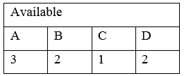
The updated Work matrix is,
Work
A | B | C | D
5 | 3 | 2 | 2
Step-2
Step 2:
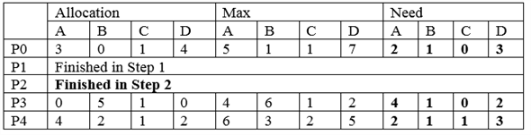
Now, the Need for P3 is less than Work, so, P3 will be allocated the needed resources and it will be finished. After finishing of P3, all allocated resources of it, will be added to the Work matrix. So, the current scenario is,
| Allocation | Max | Need
---|---|---|---
| A | B | C | D | A | B | C | D | A | B | C | D
P0 | Finished in step 1
P1 | 3 | 1 | 2 | 1 | 5 | 2 | 5 | 2 | 2 | 1 | 3 | 1
P2 | 2 | 1 | 0 | 3 | 2 | 3 | 1 | 6 | 0 | 2 | 1 | 3
P3 | Finished in step 2
P4 | 1 | 4 | 3 | 2 | 3 | 6 | 6 | 5 | 2 | 2 | 3 | 3
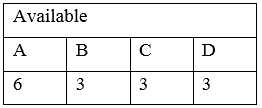
The Work matrix is,
Work
A | B | C | D
6 | 6 | 3 | 4
Step-3
Step 3:
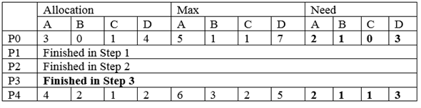
After allocating P0 and P3, P1, P2 and P4 can be in any sequence as all of their need is less than available.
Now, the Need for P4 is less than Work, so, P4 will be allocated the needed resources and it will be finished. After finishing of P4, all allocated resources of it, will be added to the Work matrix.
Step-4
So, the current scenario is,
| Allocation | Max | Need
---|---|---|---
| A | B | C | D | A | B | C | D | A | B | C | D
P0 | Finished in step 1
P1 | 3 | 1 | 2 | 1 | 5 | 2 | 5 | 2 | 2 | 1 | 3 | 1
P2 | 2 | 1 | 0 | 3 | 2 | 3 | 1 | 6 | 0 | 2 | 1 | 3
P3 | Finished in step 2
P4 | Finished in step 3
The Work matrix is,
Work
A | B | C | D
7 | 10 | 6 | 6
Step-5
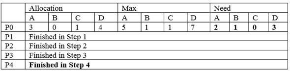
Step 4:
Now, the Need for P1 is less than Work, so, P1 will be allocated the needed resources and it will be finished. After finishing of P1, all allocated resources of it, will be added to the Work matrix.
So, the current scenario is,
| Allocation | Max | Need
---|---|---|---
| A | B | C | D | A | B | C | D | A | B | C | D
P0 | Finished in step 1
P1 | Finished in step 4
P2 | 2 | 1 | 0 | 3 | 2 | 3 | 1 | 6 | 0 | 2 | 1 | 3
P3 | Finished in step 2
P4 | Finished in step 3
The Work matrix is,
Work
A | B | C | D
10 | 11 | 8 | 7
Step-6
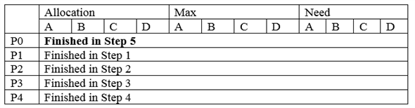
Step 5:
Now, the Need for P2 is less than Work, so, P2 will be allocated the needed resources and it will be finished. After finishing of P2, all allocated resources of it, will be added to the Work vector.
So, the current scenario is,
| Allocation | Max | Need
---|---|---|---
| A | B | C | D | A | B | C | D | A | B | C | D
P0 | Finished in step 1
P1 | Finished in step 4
P2 | Finished in step 5
P3 | Finished in step 2
P4 | Finished in step 3
The Work matrix is,
Work
A | B | C | D
12 | 12 | 8 | 10
So, all processes will be finished safely and there is no deadlock. The safe sequence will be,
P0 P3 P4 P1 P2.
Step-7
For a request from P1:
The request from P1 for resources < 1, 1, 0, 0> refers to the Request vector for P1 as given below,
Request
A | B | C | D
1 | 1 | 0 | 0
The snapshot of the system and Need matrix is,
| Allocation | Max | Need
---|---|---|---
| A | B | C | D | A | B | C | D | A | B | C | D
P0 | 2 | 0 | 0 | 1 | 4 | 2 | 1 | 2 | 2 | 2 | 1 | 1
P1 | 3 | 1 | 2 | 1 | 5 | 2 | 5 | 2 | 2 | 1 | 3 | 1
P2 | 2 | 1 | 0 | 3 | 2 | 3 | 1 | 6 | 0 | 2 | 1 | 3
P3 | 1 | 3 | 1 | 2 | 1 | 4 | 2 | 4 | 0 | 1 | 1 | 2
P4 | 1 | 4 | 3 | 2 | 3 | 6 | 6 | 5 | 2 | 2 | 3 | 3
The availability matrix is,
Available
Step-8
A | B | C | D
3 | 3 | 2 | 1
• The Need of P1 is greater than the Request from P1 and Available matrix is also greater than the Request from P1. This means, P1 has not requested more resources than its maximum limit and currently system is able to satisfy the request.
• The system will pretend to make the allocation and will check whether this allocation leads to safe state or not. If it does not lead to sate state then the system will not confirm the allocation. The changes will be:
| Allocation | Max | Need
---|---|---|---
| A | B | C | D | A | B | C | D | A | B | C | D
P0 | 2 | 0 | 0 | 1 | 4 | 2 | 1 | 2 | 2 | 2 | 1 | 1
P1 | 4 | 2 | 2 | 1 | 5 | 2 | 5 | 2 | 1 | 0 | 3 | 1
P2 | 2 | 1 | 0 | 3 | 2 | 3 | 1 | 6 | 0 | 2 | 1 | 3
P3 | 1 | 3 | 1 | 2 | 1 | 4 | 2 | 4 | 0 | 1 | 1 | 2
P4 | 1 | 4 | 3 | 2 | 3 | 6 | 6 | 5 | 2 | 2 | 3 | 3
The Availability matrix is,
Available
A | B | C | D
2 | 2 | 2 | 1
Now, check that this allocation results in a safe or unsafe state. According to safety algorithm, Work = Availability.
Step 1:
Now, the Need for P0 is less than Work, so, P0 will be allocated the needed resources and it will be finished. After finishing of P0, all allocated resources of it, will be added to the Work matrix.
The changes will be,
| Allocation | Max | Need
---|---|---|---
| A | B | C | D | A | B | C | D | A | B | C | D
P0 | Finished in step 1
P1 | 4 | 2 | 2 | 1 | 5 | 2 | 5 | 2 | 1 | 0 | 3 | 1
P2 | 2 | 1 | 0 | 3 | 2 | 3 | 1 | 6 | 0 | 2 | 1 | 3
P3 | 1 | 3 | 1 | 2 | 1 | 4 | 2 | 4 | 0 | 1 | 1 | 2
P4 | 1 | 4 | 3 | 2 | 3 | 6 | 6 | 5 | 2 | 2 | 3 | 3
The Work matrix is,
Work
A | B | C | D
4 | 2 | 2 | 2
Step-9
Step 2:
Now, the Need for P3 is less than Work, so, P3 will be allocated the needed resources and it will be finished. After finishing of P3, all allocated resources of it, will be added to the Work matrix.
The changes will be,
| Allocation | Max | Need
---|---|---|---
| A | B | C | D | A | B | C | D | A | B | C | D
P0 | Finished in step 1
P1 | 4 | 2 | 2 | 1 | 5 | 2 | 5 | 2 | 1 | 0 | 3 | 1
P2 | 2 | 1 | 0 | 3 | 2 | 3 | 1 | 6 | 0 | 2 | 1 | 3
P3 | Finished in step 2
P4 | 1 | 4 | 3 | 2 | 3 | 6 | 6 | 5 | 2 | 2 | 3 | 3
The Work matrix is,
Work
A | B | C | D
5 | 5 | 3 | 4
Step-10
Step 3:
After allocating P0 and P3, P1, P2 and P4 can be in any sequence as all of their need is less than Work.
Now, the Need for P4 is less than Work, so, P4 will be allocated the needed resources and it will be finished. After finishing of P4, all allocated resources of it, will be added to the Work matrix.
The changes will be:
| Allocation | Max | Need
---|---|---|---
| A | B | C | D | A | B | C | D | A | B | C | D
P0 | Finished in step 1
P1 | 4 | 2 | 2 | 1 | 5 | 2 | 5 | 2 | 1 | 0 | 3 | 1
P2 | 2 | 1 | 0 | 3 | 2 | 3 | 1 | 6 | 0 | 2 | 1 | 3
P3 | Finished in step 2
Step-11
P4 | Finished in step 3
The Work matrix is,
Work
A | B | C | D
6 | 9 | 6 | 6
Step-12
Step 4:
Now, the Need for P1 is less than Work, so, P1 will be allocated the needed resources and it will be finished. After finishing of P1, all allocated resources of it, will be added to the Work matrix. The changes will be:
| Allocation | Max | Need
---|---|---|---
| A | B | C | D | A | B | C | D | A | B | C | D
P0 | Finished in step 1
P1 | Finished in step 4
P2 | 2 | 1 | 0 | 3 | 2 | 3 | 1 | 6 | 0 | 2 | 1 | 3
P3 | Finished in step 2
P4 | Finished in step 3
The Work matrix is,
Work
A | B | C | D
10 | 11 | 8 | 7
Step-13
Step 5:
Now, the Need for P2 is less than Work, so, P2 will be allocated the needed resources and it will be finished. After finishing of P2, all allocated resources of it, will be added to the Work matrix.
The changes will be,
| Allocation | Max | Need
---|---|---|---
| A | B | C | D | A | B | C | D | A | B | C | D
P0 | Finished in step 1
P1 | Finished in step 4
P2 | Finished in step 5
P3 | Finished in step 2
P4 | Finished in step 3
The Work matrix is,
Work
A | B | C | D
12 | 12 | 8 | 10
So, all processes are completed without deadlock.
Step-14
Hence, the system will be in the safe state if the request of P1 is granted. The system will grant the request.
Step-15
c.
For a request from P4:
The request from P4 for resources <0, 0, 2, 0> refers to the Request vector for P4 as given below,
Request
A | B | C | D
0 | 0 | 2 | 0
The snapshot of the system and Need matrix is,
| Allocation | Max | Need
---|---|---|---
| A | B | C | D | A | B | C | D | A | B | C | D
P0 | 2 | 0 | 0 | 1 | 4 | 2 | 1 | 2 | 2 | 2 | 1 | 1
P1 | 3 | 1 | 2 | 1 | 5 | 2 | 5 | 2 | 2 | 1 | 3 | 1
P2 | 2 | 1 | 0 | 3 | 2 | 3 | 1 | 6 | 0 | 2 | 1 | 3
P3 | 1 | 3 | 1 | 2 | 1 | 4 | 2 | 4 | 0 | 1 | 1 | 2
P4 | 1 | 4 | 3 | 2 | 3 | 6 | 6 | 5 | 2 | 2 | 3 | 3
The Availability matrix is,
Available
A | B | C | D
3 | 3 | 2 | 1
• Now, the Need of P4 is greater than the Request from P4 and Available matrix is also greater than the Request from P4. This means, P4 has not requested more resources than its maximum limit and currently system is able to satisfy the request.
• The system will pretend to make the allocation and will check whether this allocation leads to safe state or not. If it does not lead to sate state then the system will not confirm the allocation. The changes will be,
| Allocation | Max | Need
---|---|---|---
| A | B | C | D | A | B | C | D | A | B | C | D
P0 | 2 | 0 | 0 | 1 | 4 | 2 | 1 | 2 | 2 | 2 | 1 | 1
P1 | 3 | 1 | 2 | 1 | 5 | 2 | 5 | 2 | 2 | 1 | 3 | 1
P2 | 2 | 1 | 0 | 3 | 2 | 3 | 1 | 6 | 0 | 2 | 1 | 3
P3 | 1 | 3 | 1 | 2 | 1 | 4 | 2 | 4 | 0 | 1 | 1 | 2
P4 | 1 | 4 | 5 | 2 | 3 | 6 | 6 | 5 | 2 | 2 | 1 | 3
The Availability matrix is,
Available
A | B | C | D
3 | 3 | 0 | 1
No other process can be satisfied with the current Work resources.
Step-16
So, the system will be in unsafe state if the request of P4 is granted. Hence, the system will reject the request.
Problem 24
Step-1
An algorithm that examines the state of the system to determine whether a dead lock has occurred. An algorithm to recover from dead lock
Detection algorithm should be invoked frequently. Resources allocated to deadlock processes will be idle until the deadlock can be broken. The number of processes involved in the dead lock cycle may grow.
If detection algorithm is involved for every resource request, it will incur considerable overhead in computation time. The algorithms whenever invoked, CPU utilization drops below 40%. Hence system throughput cripples due to dead lock and this causes CPU utilizations to drop.
Problem 25
Step-1
Pseudocode using semaphores to prevent deadlock:
The following is the pseudocode to prevent deadlock using deadlock.
// Semaphore value to cross the bridge
semaphore allowed_to_cross_bridge = 1;
// Function definition
void go_into_bridge()
{
// Suspend the process of crossing the birdge
allowed_to_cross_bridge.wait();
}
// Function definition
void way_out_of_bridge()
{
// Resume the suspended process
allowed_to_cross_bridge.signal();
}
Step-2
Explanation:
• The variable “allowed_to_cross_bridge” is represented by process waiting in queue.
• During entry of the threads into the queue, a semaphore is coupled with each thread.
• In the semaphore “go_into_bridge()” function, the process (village) which entered first into processor (bridge) will get executed (crossing the bridge) and followed by that the process next in the queue will get suspended using wait() operation.
• In the semaphore “way_out_of_bridge()” function, the process which was suspended will be awakened and allowed to get executed (crossing the bridge).
Problem 26
Step-1
Pseudocode using semaphores to prevent deadlock:
// semaphore value to cross the bridge
Semaphore allowed_to_cross_bridge=1;
// function definition
Void go_into_bridge()
{
// suspended the process of crossing the bridge
Allowed_to_cross_bridge.wait();
}
//function definition
Void way_out_of_bridge()
{
// resume the suspended process
Allow_to_cross_bridge.signal();
}
Step-2
To the above code add no_waiting_north, no_waiting_south and previous inorder to know which side has crossed most recently. If south side van is crossed recently then north side van is given chance to cross the bridge and south side van will be in waiting state until there is no van on the north side or vice versa.
If a car finishes crossing on the south side and no car waiting on the south side then the car on the north side will go or vice-versa.
monitor bridge
{
int no_waiting_north=0;
int no_waiting_south=0;
int on_bridge=0;
ok_to_crossbridge();
{}
int previous=0;
cross_bridge_south()
{
no_waiting_south++;
while( on_bridge || previous==0 && no_waiting_north>0)
{
allowed_to_cross_bridge.wait();
on_bridge=1;
no_waiting_south—;
previous=0;
}
leave_bridge_south()
{
on_bridge=0;
allowed_to_cross_bridge.announce();
}
}
cross_bridge_north()
{
no_waiting_north++;
while( on_bridge || previous==0 && no_waiting_south>0)
{
allowed_to_cross_bridge.wait();
on_bridge=1;
no_waiting_north—;
previous=0;
}
leave_bridge_north()
{
on_bridge=0;
allowed_to_cross_bridge.announce();
}
}
Problem 27
Step-1
Program Plan:
• Define user define datatype which takes two possible directions that are possible on the bridge.
• Define the method init_synch which takes two value as an argument which initialize the synchronization variables that is a mutex and a condition variable.
• Define the method destroy_synch which takes two value as an argument which destroy the synchronization variables that is a mutex and a condition variable.
• Define the method create_threads to simulate the farmers. Create num_north threads for the farmers from North Tunbridge and create num_south threads for the farmers from South Tunbridge.
• Define the method destroy_threads which is use for destroying the threads created.
• Define the method north_runner which takes one value as an arguments and the thread runner function for a farmer from North Tunbridge.
• Define the method south_runner which takes one value as an arguments and the thread runner function for a farmer from South Tunbridge.
• Define the method north_enter to enter the bridge from the north side.
• Define the method north_exit which exit the bridge after entering it from the north.
• Define the function south_enter which enter the bridge from the south side.
• Define the function south_exit which exit the bridge after entering it from the south.
• Define the main method from where the execution of the program begins.
Step-2
Program:
/*********************************************************** Program for designing an echo server in which * * echo server provides services to each client in a * * separate request. * **********************************************************/
Include a header file for performing the operation.
// The number of farmers going north
const int NUM_NORTH = 20**;**
// The number of farmers going south
const int NUM_SOUTH = 20**;**
// The maximum amount of time taken to cross the bridge
const int MAX_CROSSING_TIME = 5**;**
// Mutex used to prevent a deadlock
static pthread_mutex_t s_mutex**;**
// Condition variable used to notify
// that the bridge is free
static pthread_cond_t s_cond**;**
// The number of farmers crossing north on the bridge
static int s_num_north**;**
// The number of farmers crossing south on the bridge
static int s_num_south**;**
// The number of farmers waiting to cross
// the bridge from the north direction
static int s_num_north_waiting**;**
// The number of farmers waiting to cross
// the bridge from the south direction
static int s_num_south_waiting**;**
Define user define datatype which takes two possible directions that are possible on the bridge.
enum Direction
{
NORTH**,**
SOUTH**,**
};
// The current direction on the bridge
static enum Direction s_direction**;**
Declare the method init_synch which takes two values as an arguments and it is use for initializing the synchronization variables.
static int init_synch**(** pthread_mutex_t ***** pmutex**,**
pthread_cond_t ***** pcond**);**
Declare the method destroy_synch which takes two values as an arguments and it is use for destroying the synchronization variables.
static void destroy_synch**(** pthread_mutex_t ***** pmutex**,**
Step-3
pthread_cond_t ***** pcond**);**
Declare the method create_threads which is use for creating the threads.
static int create_threads**(** pthread_attr_t ***** attr**,**
pthread_t ***** north_ids**,**
pthread_t ***** south_ids**,**
int ***** north_nums**,**
int ***** south_nums**,**
const int num_north**,**
const int num_south**);**
Declare the method destroy_threads which is use for destroying the threads.
static void destroy_threads**(** pthread_t ***** north_ids**,**
pthread_t ***** south_ids**,**
int ***** north_nums**,**
int ***** south_nums**,**
const int num_north**,**
const int num_south**);**
Declare the method north_runner which takes one value as an argument. This function tracks the farmer going north.
static void ***** north_runner**(** void ***** param**);**
Declare the method south_runner which takes one values as an argument. This function tracks the farmer going south.
static void ***** south_runner**(** void ***** param**);**
Declare the method north_enter which takes one values as an argument. Farmer enter the bridge from the north direction.
static void north_enter**(** void**);**
Declare the method north_exit which takes one values as an argument. Farmer exits the bridge after entering it from the north direction.
static void north_exit**(** void**);**
Declare the method south_enter which takes one values as an argument. Farmer enter the bridge from the south direction.
static void south_enter**(** void**);**
Declare the method south_exit which takes one values as an argument. Farmer exits the bridge after entering it from the south direction.
static void south_exit**(** void**);**
Define the main method from where the execution of the program begins.
int main**(** void**)**
{
// The pthread attributes
pthread_attr_t attr**;**
// An array for storing the thread ids
pthread_t north_ids**[** NUM_NORTH**];**
pthread_t south_ids**[** NUM_SOUTH**];**
// An array for storing the thread numbers
int north_nums**[** NUM_NORTH**];**
int south_nums**[** NUM_SOUTH**];**
// Initialize the synchronization variables
if ( init_synch**( &s_mutex,** & s_cond**)** < 0**)**
return 1**;**
// Initialize pthreads
if ( pthread_attr_init**( &attr)** != 0**)**
{
fputs**(** “pthread_attr_init didn’t work\n”,
stderr**);**
// Destroy the synchronization variables
destroy_synch**( &s_mutex,** & s_cond**);**
return 2**;**
}
// Seed the random number generator
// with the current time
srand**(** time**(NULL));**
// No farmers are on the bridge
s_num_north = s_num_south = 0**;**
// No farmers are either waiting to cross the bridge
s_num_north_waiting = s_num_south_waiting = 0**;**
// Set the initial direction to north
s_direction = NORTH**;**
// Create the threads/farmers
if ( create_threads**( &attr,**
north_ids**,** south_ids**,**
north_nums**,** south_nums**,**
NUM_NORTH**,** NUM_SOUTH**)** < 0**)**
{
fputs**(** “Couldn’t create threads\n”, stderr**);**
// De-initialize pthreads
pthread_attr_destroy**( &attr);**
// Destroy the synchronization variables
destroy_synch**( &s_mutex,** & s_cond**);**
return 3**;**
}
Call the methods destroy_threads for the threads/farmers to exit.
destroy_threads**(** north_ids**,** south_ids**,**
north_nums**,** south_nums**,**
NUM_NORTH**,** NUM_SOUTH**);**
// De-initialize pthreads
pthread_attr_destroy**( &attr);**
// Destroy the synchronization variables
destroy_synch**( &s_mutex,** & s_cond**);**
return 0**;**
}
Define the method init_synch which takes two value as an argument which initialize the synchronization variables that is a mutex and a condition variable.
int init_synch**(** pthread_mutex_t ***** pmutex**,**
pthread_cond_t ***** pcond**)**
{
if (! pmutex || ! pcond**)**
return - 1**;**
// Initialize the mutex
if ( pthread_mutex_init**(** pmutex**,** NULL**)** != 0**)** {
fputs**(** “pthread_mutex_init didn’t work\n”,
stderr**);**
return - 2**;**
}
// Initialize the condition variable
if ( pthread_cond_init**(** pcond**,** NULL**)** != 0**)** {
fputs**(** “pthread_cond_init blew\n”, stderr**);**
// Destroy the mutex
pthread_mutex_destroy**( &s_mutex);**
return - 3**;**
}
return 0**;**
}
Define the method destroy_synch which takes two value as an argument which destroy the synchronization variables that is a mutex and a condition variable.
void destroy_synch**(** pthread_mutex_t ***** pmutex**,**
pthread_cond_t ***** pcond**)**
{
if ( pcond**)**
// Destroy the condition variable
pthread_cond_destroy**(** pcond**);**
if ( pmutex**)**
// Destroy the mutex
pthread_mutex_destroy**(** pmutex**);**
}
Define the method create_threads to simulate the farmers. Create num_north threads for the farmers from North Tunbridge and create num_south threads for the farmers from South Tunbridge.
int create_threads**(** pthread_attr_t ***** attr**,**
pthread_t ***** north_ids**,**
pthread_t ***** south_ids**,**
int ***** north_nums**,**
int ***** south_nums**,**
const int num_north**,**
const int num_south**)**
{
// Used to index into the thread_ids array
int index**;**
// The value returned by functions
int ret**;**
if (! attr || ! north_ids || ! south_ids
|| ! north_nums || ! south_nums
|| num_north < 0 || num_south < 0**)**
return - 1**;**
// Loop to create the threads
for ( index = 0**;** index < num_north
|| index < num_south**;** index**++)**
{
// Does a north thread have to be created?
if ( index < num_north**)**
{
// Store the thread number
north_nums**[** index**]** = index + 1**;**
// Create a thread
ret = pthread_create**( &north_ids[** index**],**
attr**,** north_runner**,**
north_nums + index**);**
if ( ret != 0**)**
{
printf**(** “Couldn’t create north thread ”
“number %d\n”, index + 1**);**
north_ids**[** index**]** = - 1**;**
}
}
// Does a south thread have to be created?
if ( index < num_south**)**
{
// Store the thread number
south_nums**[** index**]** = index + 1**;**
// Create a thread
ret = pthread_create**(** south_ids + index**,**
attr**,** south_runner**,**
south_nums + index**);**
if ( ret != 0**)**
{
printf**(** “Couldn’t create south thread ”
“number %d\n”, index + 1**);**
south_ids**[** index**]** = - 1**;**
}
}
}
return 0**;**
}
Define the method destroy_threads which is use for destroying the threads created.
void destroy_threads**(** pthread_t ***** north_ids**,**
pthread_t ***** south_ids**,**
int ***** north_nums**,**
int ***** south_nums**,**
const int num_north**,**
const int num_south**)**
{
// Used to index into the thread_ids array
int index**;**
// The value returned by functions
int ret**;**
Check the condition using the if statement.
if (! north_ids || ! south_ids
|| ! north_nums || ! south_nums**)**
return**;**
// Loop to wait for the threads to exit
for ( index = 0**;** index < NUM_NORTH
|| index < NUM_SOUTH**;** index**++)**
{
// Does a north thread have to be waited for?
if ( index < NUM_NORTH & & north_ids**[** index**]** >= 0**)**
{
// Wait for a thread to exit
ret = pthread_join**(** north_ids**[** index**],** NULL**);**
if ( ret != 0**)**
printf**(** “pthread_join didn’t work for ”
“north thread num %2d\n”,
north_nums**[** index**]);**
}
// Does a south thread have to be waited for?
if ( index < NUM_SOUTH & & south_ids**[** index**]** >= 0**)**
{
// Wait for a thread to exit
ret = pthread_join**(** south_ids**[** index**],** NULL**);**
if ( ret != 0**)**
printf**(** “pthread_join didn’t work for ”
“south thread num %2d\n”,
south_nums**[** index**]);**
}
}
}
Define the method north_runner which takes one value as an arguments and the thread runner function for a farmer from North Tunbridge.
void ***** north_runner**(** void ***** param**)**
{
// Get the number of this thread
int num = (( typeof( &num)) param*);**
printf**(** “Farmer #%2d from North Tunbridge ”
“waiting…\n”, num**);**
// Enter the bridge
north_enter**();**
printf**(** “Farmer #%2d from North Tunbridge ”
“crossing the bridge…\n”, num**);**
// Sleep to simulate crossing the bridge
sleep**(** rand**()** % MAX_CROSSING_TIME + 1**);**
// Exit the bridge
north_exit**();**
printf**(** “Farmer #%2d from North Tunbridge ”
“crossed the bridge\n”, num**);**
// Exit from this thread
pthread_exit**(** 0**);**
}
Define the method south_runner which takes one value as an arguments and the thread runner function for a farmer from South Tunbridge.
void ***** south_runner**(** void ***** param**)**
{
// Get the number of this thread
int num = (( typeof( &num)) param*);**
printf**(** “Farmer #%2d from South Tunbridge ”
“waiting…\n”, num**);**
// Enter the bridge
south_enter**();**
printf**(** “Farmer #%2d from South Tunbridge ”
“crossing the bridge…\n”, num**);**
// Sleep to simulate crossing the bridge
sleep**(** rand**()** % MAX_CROSSING_TIME + 1**);**
// Exit the bridge
south_exit**();**
printf**(** “Farmer #%2d from South Tunbridge ”
“crossed the bridge\n”, num**);**
// Exit from this thread
pthread_exit**(** 0**);**
}
Define the method north_enter to enter the bridge from the north side.
void north_enter**(** void**)**
{
// Lock the mutex
pthread_mutex_lock**( &s_mutex);**
// Increment the number of farmers
// waiting on the north side
s_num_north_waiting**++;**
while one of the following are true a. farmers crossing the bridge from the south, b. farmers are waiting on the south side and the direction is south
while ( s_num_south > 0
|| ( s_num_south_waiting > 0
& & s_direction == SOUTH**))**
// Wait on the condition variable
pthread_cond_wait**( &s_cond,** & s_mutex**);**
// Set the direction to the north
s_direction = NORTH**;**
// Decrement the farmers waiting to cross the bridge
s_num_north_waiting**—;**
// One more farmer is crossing from the north
s_num_north**++;**
// Unlock the mutex
pthread_mutex_unlock**( &s_mutex);**
}
Define the method north_exit which exit the bridge after entering it from the north.
void north_exit**(** void**)**
{
// Lock the mutex
pthread_mutex_lock**( &s_mutex);**
// Decrement the number of farmers
// crossing the bridge from the north
s_num_north**—;**
// Set the direction to the south
s_direction = SOUTH**;**
Checking the condition are no farmers crossing the bridge from the north.
if ( s_num_north == 0**)**
// Broadcast that the state of the
// condition variable has changed
pthread_cond_broadcast**( &s_cond);**
// Unlock the mutex
pthread_mutex_unlock**( &s_mutex);**
}
Define the function south_enter which enter the bridge from the south side.
void south_enter**(** void**)**
{
// Lock the mutex
pthread_mutex_lock**( &s_mutex);**
// Increment the number of farmers
// waiting on the south side
s_num_south_waiting**++;**
While one of the following is true a. farmers crossing the bridge from the north and b. farmers are waiting on the north side and the direction is north.
while ( s_num_north > 0
|| ( s_num_north_waiting > 0
& & s_direction == NORTH**))**
// Wait on the condition variable
pthread_cond_wait**( &s_cond,** & s_mutex**);**
// Set the direction to the south
s_direction = SOUTH**;**
// Decrement the farmers waiting to cross the bridge
s_num_south_waiting**—;**
// One more farmer is crossing from the south
s_num_south**++;**
// Unlock the mutex
pthread_mutex_unlock**( &s_mutex);**
}
Define the function south_exit which exit the bridge after entering it from the south.
void south_exit**(** void**)**
{
// Lock the mutex
pthread_mutex_lock**( &s_mutex);**
// Decrement the number of farmers
// crossing the bridge from the south
s_num_south**—;**
// Set the direction to the north
s_direction = NORTH**;**
Checking whether the farmer is crossing the bridge from the south or not.
if ( s_num_south == 0**)**
// Broadcast that the state of the
// condition variable has changed
pthread_cond_broadcast**( &s_cond);**
// Unlock the mutex
pthread_mutex_unlock**( &s_mutex);**
}
Step-4
Sample Output:
Farmer # 1 from North Tunbridge waiting…
Farmer # 1 from North Tunbridge crossing the bridge…
Farmer # 2 from North Tunbridge waiting…
Farmer # 2 from North Tunbridge crossing the bridge…
Farmer # 2 from South Tunbridge waiting…
Farmer # 3 from North Tunbridge waiting…
Farmer # 3 from North Tunbridge crossing the bridge…
Farmer # 3 from South Tunbridge waiting…
Farmer # 4 from North Tunbridge waiting…
Farmer # 4 from North Tunbridge crossing the bridge…
Farmer # 4 from South Tunbridge waiting…
Farmer # 5 from North Tunbridge waiting…
Farmer # 5 from North Tunbridge crossing the bridge…
Farmer # 5 from South Tunbridge waiting…
Farmer # 6 from North Tunbridge waiting…
Farmer # 6 from North Tunbridge crossing the bridge…
Farmer # 6 from South Tunbridge waiting…
Farmer # 7 from North Tunbridge waiting…
Farmer # 7 from North Tunbridge crossing the bridge…
Farmer # 7 from South Tunbridge waiting…
Farmer # 8 from North Tunbridge waiting…
Farmer # 8 from North Tunbridge crossing the bridge…
Farmer # 8 from South Tunbridge waiting…
Farmer # 9 from North Tunbridge waiting…
Farmer # 9 from North Tunbridge crossing the bridge…
Farmer # 9 from South Tunbridge waiting…
Farmer #10 from North Tunbridge waiting…
Farmer #10 from North Tunbridge crossing the bridge…
Farmer #10 from South Tunbridge waiting…
Farmer #11 from North Tunbridge waiting…
Farmer #11 from North Tunbridge crossing the bridge…
Farmer #11 from South Tunbridge waiting…
Farmer # 1 from South Tunbridge waiting…
Farmer #12 from North Tunbridge waiting…
Farmer #12 from North Tunbridge crossing the bridge…
Farmer #12 from South Tunbridge waiting…
Farmer #13 from North Tunbridge waiting…
Farmer #13 from North Tunbridge crossing the bridge…
Farmer #13 from South Tunbridge waiting…
Farmer #14 from North Tunbridge waiting…
Farmer #14 from North Tunbridge crossing the bridge…
Farmer #14 from South Tunbridge waiting…
Farmer #15 from North Tunbridge waiting…
Farmer #15 from North Tunbridge crossing the bridge…
Farmer #15 from South Tunbridge waiting…
Farmer #16 from North Tunbridge waiting…
Farmer #16 from North Tunbridge crossing the bridge…
Farmer #16 from South Tunbridge waiting…
Farmer #17 from North Tunbridge waiting…
Farmer #17 from North Tunbridge crossing the bridge…
Farmer #17 from South Tunbridge waiting…
Farmer #18 from North Tunbridge waiting…
Farmer #18 from North Tunbridge crossing the bridge…
Farmer #18 from South Tunbridge waiting…
Farmer #19 from North Tunbridge waiting…
Farmer #19 from North Tunbridge crossing the bridge…
Farmer #19 from South Tunbridge waiting…
Farmer #20 from North Tunbridge waiting…
Farmer #20 from North Tunbridge crossing the bridge…
Farmer #20 from South Tunbridge waiting…
Farmer # 5 from North Tunbridge crossed the bridge
Farmer # 6 from North Tunbridge crossed the bridge
Farmer # 8 from North Tunbridge crossed the bridge
Farmer #10 from North Tunbridge crossed the bridge
Farmer #16 from North Tunbridge crossed the bridge
Farmer # 3 from North Tunbridge crossed the bridge
Farmer #12 from North Tunbridge crossed the bridge
Farmer #13 from North Tunbridge crossed the bridge
Farmer #17 from North Tunbridge crossed the bridge
Farmer #18 from North Tunbridge crossed the bridge
Farmer # 2 from North Tunbridge crossed the bridge
Farmer # 7 from North Tunbridge crossed the bridge
Farmer # 9 from North Tunbridge crossed the bridge
Farmer # 1 from North Tunbridge crossed the bridge
Farmer #14 from North Tunbridge crossed the bridge
Farmer #15 from North Tunbridge crossed the bridge
Farmer #20 from North Tunbridge crossed the bridge
Farmer # 4 from North Tunbridge crossed the bridge
Farmer #11 from North Tunbridge crossed the bridge
Farmer #19 from North Tunbridge crossed the bridge
Farmer # 2 from South Tunbridge crossing the bridge…
Farmer # 3 from South Tunbridge crossing the bridge…
Farmer # 4 from South Tunbridge crossing the bridge…
Farmer # 5 from South Tunbridge crossing the bridge…
Farmer # 6 from South Tunbridge crossing the bridge…
Farmer # 7 from South Tunbridge crossing the bridge…
Farmer # 8 from South Tunbridge crossing the bridge…
Farmer # 9 from South Tunbridge crossing the bridge…
Farmer #10 from South Tunbridge crossing the bridge…
Farmer #11 from South Tunbridge crossing the bridge…
Farmer # 1 from South Tunbridge crossing the bridge…
Farmer #12 from South Tunbridge crossing the bridge…
Farmer #13 from South Tunbridge crossing the bridge…
Farmer #14 from South Tunbridge crossing the bridge…
Farmer #15 from South Tunbridge crossing the bridge…
Farmer #16 from South Tunbridge crossing the bridge…
Farmer #17 from South Tunbridge crossing the bridge…
Farmer #18 from South Tunbridge crossing the bridge…
Farmer #19 from South Tunbridge crossing the bridge…
Farmer #20 from South Tunbridge crossing the bridge…
Farmer # 3 from South Tunbridge crossed the bridge
Farmer # 7 from South Tunbridge crossed the bridge
Farmer #10 from South Tunbridge crossed the bridge
Farmer # 8 from South Tunbridge crossed the bridge
Farmer #13 from South Tunbridge crossed the bridge
Farmer # 1 from South Tunbridge crossed the bridge
Farmer # 6 from South Tunbridge crossed the bridge
Farmer # 4 from South Tunbridge crossed the bridge
Farmer # 5 from South Tunbridge crossed the bridge
Farmer #14 from South Tunbridge crossed the bridge
Farmer #11 from South Tunbridge crossed the bridge
Farmer #18 from South Tunbridge crossed the bridge
Farmer #20 from South Tunbridge crossed the bridge
Farmer # 2 from South Tunbridge crossed the bridge
Farmer #19 from South Tunbridge crossed the bridge
Farmer #16 from South Tunbridge crossed the bridge
Farmer #15 from South Tunbridge crossed the bridge
Farmer #12 from South Tunbridge crossed the bridge
Farmer # 9 from South Tunbridge crossed the bridge
Farmer #17 from South Tunbridge crossed the bridge